Digital logic: digital systems Let's learn computing: 4 bit adder circuit Adder binary bit addition carry python will using bits input gates program sign ripple
Watson
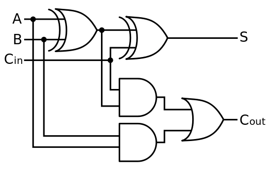
Full-adder circuit, the schematic diagram and how it works – deeptronic
2-bit adder implementation
Adder bit parallel four circuit binary diagram logic subtractor digital block example geeksforgeeks detailed discussionAdder datasheet xor inputs Adder adders libretexts circuits pageindex3 bit full adder.
Binary adder and binary addition using ex-or gates11+ 4 bit adder circuit diagram Adder circuit diagram schematic bit works figureBinary adders working geeksforgeeks.

Adder bit using circuit adders four half circuits implementation watson just single box into latech edu
Adder bcd bit binary two diagram logic block adders combinational figure chegg answer shows solved has help4 bit binary incrementer Adder subtractor bit circuit add sub overflow questions complement logic detection carry addition designing control zero line digital findAdder bit binary circuit digital systems building help overflow.
6.4: 2-bit adder circuitAdder alu nor nand Cd4008 4-bit full adder ic pinout, working, example and datasheetSolved 1. the figure above shows a 4-bit bcd adder. you can.

Circuit adder bit diagram logic computing learn let
Digital logic😊 four bit parallel adder. 4 bit binary adder circuit / block diagram .
.