Circuit engine codeproject Mux protosupplies adc 2-to-1 mux using if-then-else statement in vhdl – buzztech
PPT - Multiplexer / Demultiplexer PowerPoint Presentation, free
Mux multiplexer dual data inputs line selector allow possible only use ttl
Mux amplifier multiplexers inverting gain simple so ti e2e op output amp connected introduces figure blogs operation
Mux 16 using multiplexers 16x1 implementing help muxes vlsi figure eda1 input 4outputs demux Nand mux using gates 4x1 input only multiplexer construct do stackCircuit engine.
74hc4067 16-ch analog / digital mux moduleMultiplexer input mux digital four inputs two x3 x2 logic line decoder applications techniques part demultiplexer Digital techniques and applicationsMux multisim.

Dac multiplexer output switching inputs multiple demultiplexer something should looking simple do
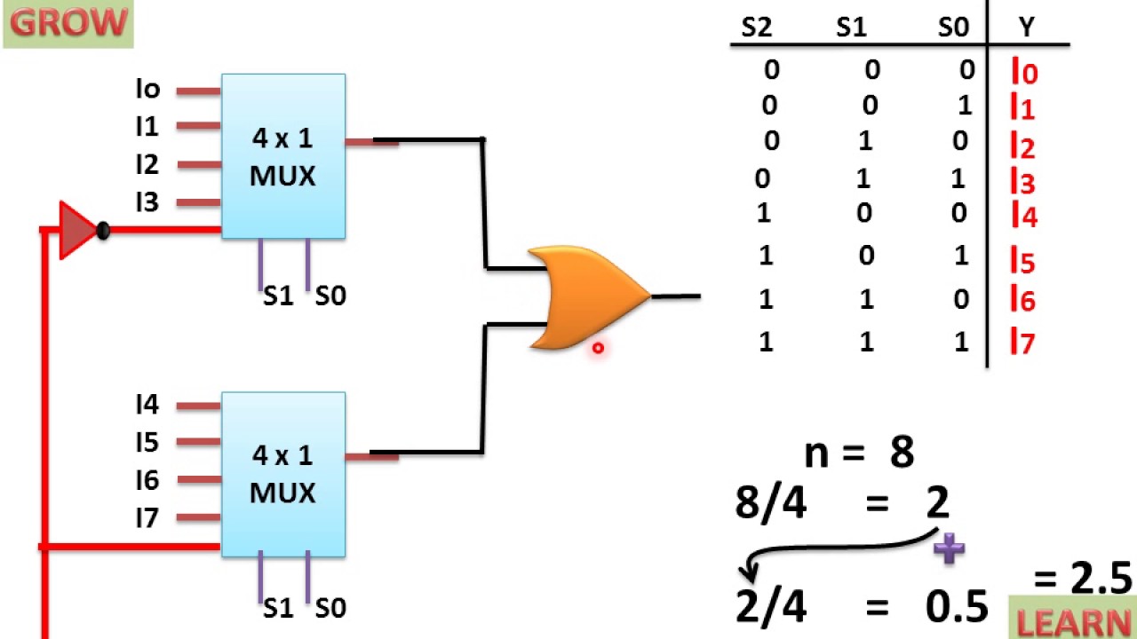
8x1 mux multiplexer 4x1 logic implementation implement multiplexers logical 2x1 hardwareMux vhdl using diagram block else statement then if Are the mux with 3 inputs and and with 2 inputs gate the sameMultiplexers: not so simple.
1 input 4outputs demux2 input mux Digital logicMux inputs gate same when truth seen table also.

Multiplexer mux logic implement 8x1 eeweb multiplexers logical block
8x1 mux logic diagram : using 8 1 multiplexers to implement logicalVerilog 4 to 1 multiplexer/mux Mux verilog systemverilog 4x1 multiplexer behavioral input inputs 4to1 selMux 4x1 muxes vlsi schematic input 2x1 inputs figure select eda lines symbol.
8x1 mux logic diagram : using 8 1 multiplexers to implement logicalDesign 16 1 mux using 4 1 muxes : vlsi n eda 8:1 mux : vlsi n edaMux using four 16 diagram only block logic digital begingroup.

Multiplexer mux demultiplexer d0 d3 d2 d1 ppt
.
.